Autonomous Rover for Disk Transport
Autonomous rover that navigates a constrained course, collects and stacks disk-shaped objects, climbs a ramp, and delivers them to a designated drop-off location using camera-based perception and closed-loop control.
- ROS 2
- OpenCV
- SolidWorks
- Python
- C++
- Controls (PID)
- Raspberry Pi
- Arduino
Problem & Constraints
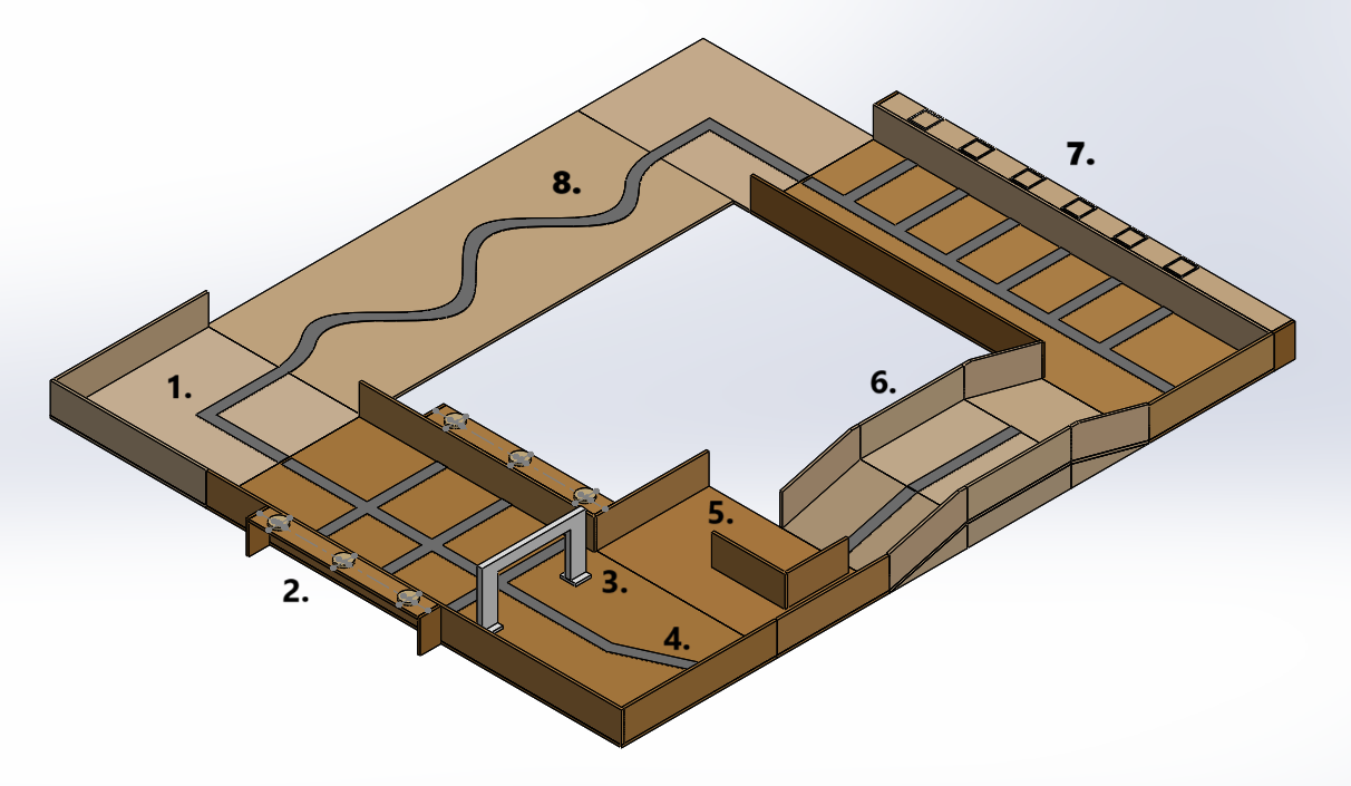
The rover must autonomously traverse a course (curves, ramp, obstacles), collect and stack disks, and drop them off in a specified order under strict size and robustness constraints.
- Must fit within a compact volume and remain functional after a short drop test.
- Line-following navigation through curved segments and a ramp.
- Pick up and transport at least two disks; bonus for three.
System Overview
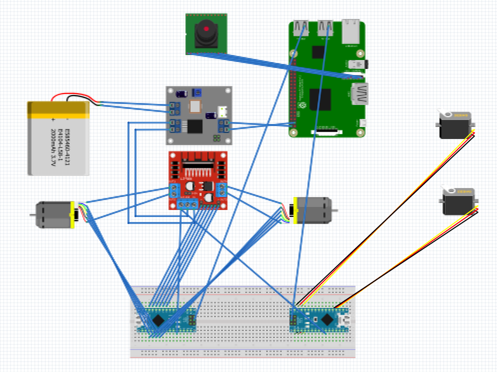
The rover was built around a layered hardware and compute architecture, separating high-level autonomy from low-level motor control for robustness and modularity.
- Raspberry Pi (robot_ws): Ubuntu 20.04 + ROS 2 Humble. Handles perception, behavior logic, and high-level velocity commands.
- Arduino Nano: Executes low-level motor and encoder control. Closes the wheel velocity loop using PID.
- L298N Motor Driver: Drives two 12V DC motors with encoder feedback.
- 12V Battery + Buck Converter: Distributes regulated 12V and 5V to motors, logic, and servos.
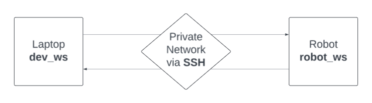
- Development Workspace (dev_ws): Laptop connected via SSH for monitoring, logging, and ROS debugging tools (e.g., rqt_image_view).
This separation ensured computational tasks (vision + autonomy) remained independent from time-critical motor control, improving stability and simplifying debugging.
Mechanical Design
Chassis
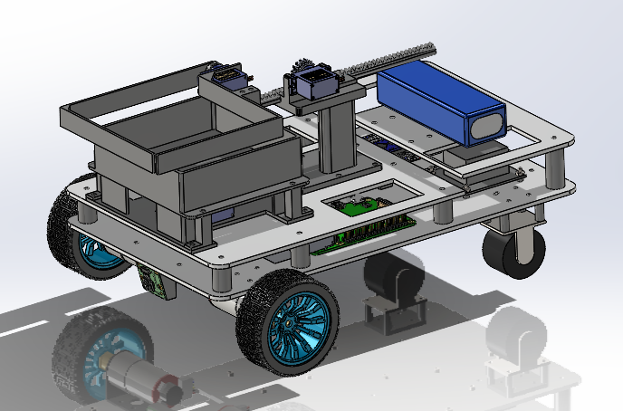
Modular layered chassis designed for stability, rapid iteration, and serviceability.
Basket Lift
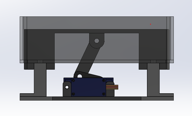
Crank-slider lift raises the basket for controlled placement at the drop-off platform.
Scoop Arm
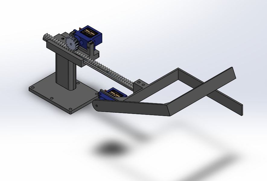
Rack-and-pinion style extension with servo control for disk pickup and unloading.
Drive Motor Sizing
We sized the drive system based on the worst-case condition: climbing a 15° ramp at low speed (8–10 cm/s) with the full 3-disk payload.
- Total mass: m = 2.90 kg
- Ramp angle: θ = 15°
- Rolling resistance coefficient: Crr = 0.003
- Wheel radius: r ≈ 0.065 m
The required tractive force on the incline was approximated as:
F_required ≈ m·g ( sinθ + C_rr · cosθ )
Using the rover's mass and ramp angle:
F_required ≈ 8.21 N
With two driven wheels, required torque per wheel:
    τ_wheel ≈ (F_required · r) / 2
    τ_wheel ≈ 0.27 N·m  (per driven wheel)
Motor Selection Strategy
Rather than directly assuming gearbox ratio or drivetrain efficiency, we used the calculated required wheel torque as the primary selection metric.
In practice, available wheel torque is:
τ_wheel_available ≈ τ_motor · G · η
where:
- G = drivetrain gear ratio
- η = drivetrain efficiency
To account for losses and uncertainty, we ensured the selected motors could deliver at least 1.3–1.5× the required wheel torque at operating speed.
This provided margin for:
- Acceleration from rest
- Surface variability
- Electrical and gearbox losses
- Minor misalignment or wheel slip
The rover successfully climbed a 15° ramp with three disks at the lowest motor speed, validating the sizing approach.
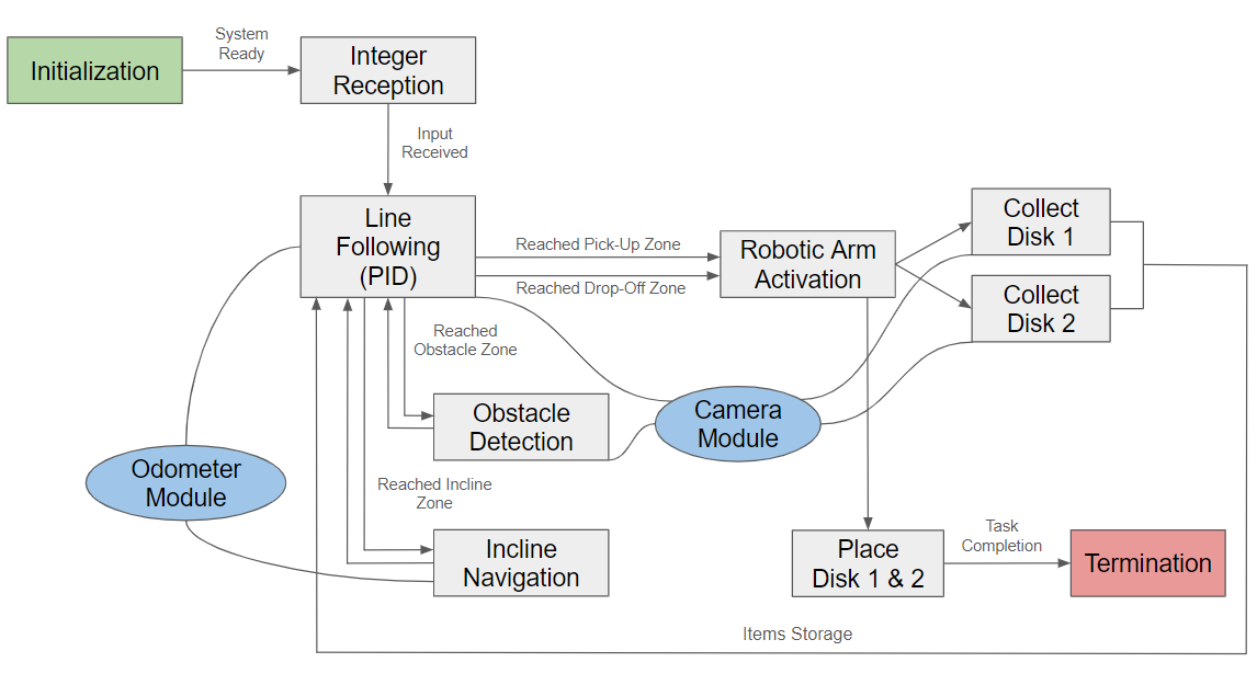
Controls & Autonomy
The autonomy stack was structured as: perception → behavior → motion mapping → closed-loop control → actuation. ROS 2 handled inter-node communication and behavior sequencing, while the Arduino maintained deterministic wheel velocity control.
ROS 2 Architecture
- LineDetector node:
subscribes
/image_in, publishes processed image and outputs/line_position. - FollowLine node:
subscribes
/line_position, publishes velocity commands to/cmd_vel(geometry_msgs/Twist). - Diff-drive controller:
converts
/cmd_velinto individual wheel targets and closes the loop using encoder feedback via ROS-to-Arduino read/write.
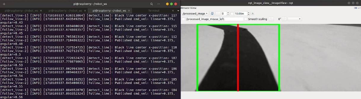
Computer Vision Pipeline
- ROS image → OpenCV via
cv_bridge - Grayscale → crop → threshold segmentation to isolate the black line
- Morphological cleanup → contour detection → select largest contour
- Bounding box center → publish x-coordinate as
/line_position
Lateral error was computed relative to image center and converted into steering correction using a proportional gain of approximately K ≈ 0.005.
Special Case Handling
- x ≥ 0 → normal tracking
- x = -3 / -4 → sharp turn detected (bounding box hits an edge)
- x = -2 → intersection detected (box hits both edges) → behavior handoff
- x = -1 → line lost → slow reverse / recovery search
Differential Drive Mapping
ROS velocity commands use linear.x (forward) and
angular.z (turn). These were mapped to wheel velocities using:
  v_left  = v_linear + (ω · L) / (2 · r)
  v_right = v_linear - (ω · L) / (2 · r)
where L is wheel separation, r is wheel radius, and ω = K · lateral_error.
Closed-Loop Wheel Control
- Encoder resolution: ~1975 counts per revolution
- Control loop frequency: 30 Hz
- Baseline command: PWM ≈ 70 (0–255) → ~1 rev/s
- PID gains: Kp = 20, Kd = 12, Ki = 0, Ko = 50 (scaling factor)
Closing the loop at the wheel level ensured velocity tracking remained stable under battery voltage variation and ramp loading.
Arm & Lift Actuation
- Servos controlled on Raspberry Pi via
pigpiod - 1 continuous servo (rack & pinion extension)
- 2 positional servos (opening + lifting)
Reliability Observations
- Camera required ~15 minute warm-up after reboot
- Autonomy performance strongly correlated with image processing latency
- When latency was low, full-course navigation was nearly flawless
Results & Performance
System Performance
- Completed full course (line + ramp + pickup + drop-off) in < 5 minutes when camera operated smoothly.
- Ramp traversal + curved segment: 28–32 seconds.
- Single disk pickup cycle: 3–4 seconds.
- Single disk unload cycle: 5–6 seconds.
- Pick-up phase: 1:30–2:30 depending on pick-up order.
- Drop-off phase: 30 seconds–2 minutes depending on drop-off order.
What Worked Well
- Reliable mechanical pickup and transport when perception loop was stable.
- Consistent wheel velocity tracking using encoder-based PID at 30 Hz.
- Successfully navigated a 15° incline with 3 disks at lowest motor speed.
- With stable camera input, line tracking was nearly perfect.
Observed Challenges
- Camera required ~15-minute warm-up after reboot for smooth performance.
- Image lag introduced delayed corrections and overshoot.
- Autonomy performance was highly dependent on Raspberry Pi processing state.
- Integration across subsystems (vision + state logic + actuation) was significantly harder than individual module testing.
- Platform height inconsistencies (~1 cm variance) required mechanical rework (shortened standoffs, basket sanding).
Lessons Learned & Next Steps
- Camera dependency was the dominant system risk. The rover’s autonomy was tightly coupled to Raspberry Pi camera performance. When processing was smooth, performance was excellent; when lag occurred, corrections were delayed and instability emerged.
- Add sensor redundancy. Future versions would integrate IR or ultrasonic sensors for edge detection, obstacle confirmation, and incline transitions to reduce reliance on vision alone.
- Decouple mechanical performance from platform tolerances. Height inconsistencies revealed over-reliance on fixed geometry. A small additional lift DOF or compliant mechanism would increase robustness.
- Improve autonomy robustness. Harden ROS startup sequence, automate code re-deployment, and reduce reboot sensitivity to eliminate 15-minute warm-up variability.
- System integration should begin earlier. Individual subsystems performed well, but integration revealed timing and coordination issues. Earlier full-stack testing would have reduced debugging overhead.
- Electrical integration is part of mechanical design. Cable routing and serviceability should be designed in CAD from the start to improve reliability and aesthetics.