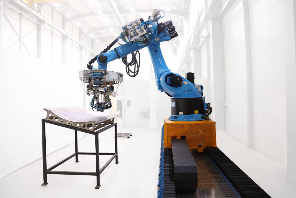
Robotic Arm for Automated Fiber Placement
Simulated an AFP task with a UR5e in PyDrake: a roller end-effector follows a surface trajectory while regulating contact forces via operational-space impedance control. The focus was contact stability — bounded forces and damped recovery — rather than pure position tracking.
- Python
- PyDrake
- Impedance Control
- Contact Modeling
- UR5e
At a Glance
Overview
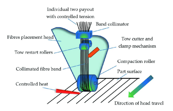
AFP lays composite tow along a prescribed path while a roller compacts material against a mold. The control challenge is maintaining consistent normal force and alignment while following a surface path under compliance, geometry mismatch, and disturbances.
- Robot: UR5e in Drake's multibody simulation
- End effector: roller modeled as a rigid body attached to the wrist
- Environment: compliant mold surface as contact geometry
- Control goal: stable force interaction + trajectory tracking via impedance control
Trajectory Generation
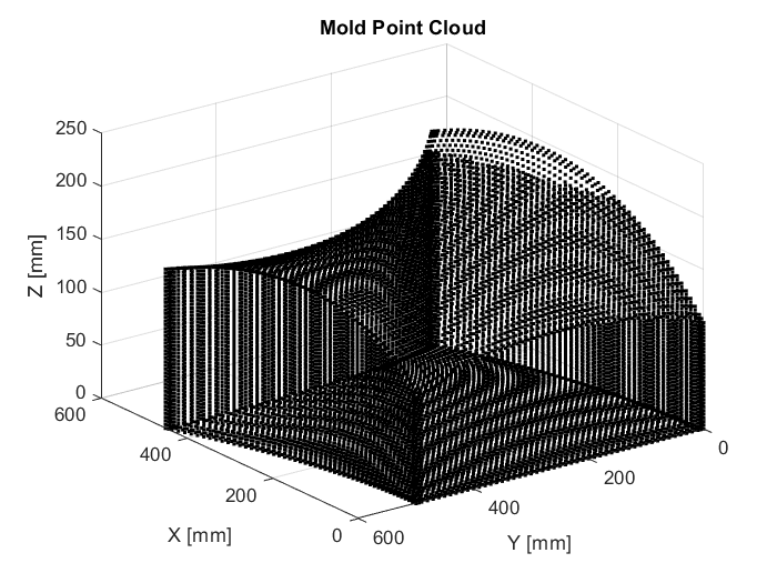
- Represent mold surface (Bezier surface or mesh)
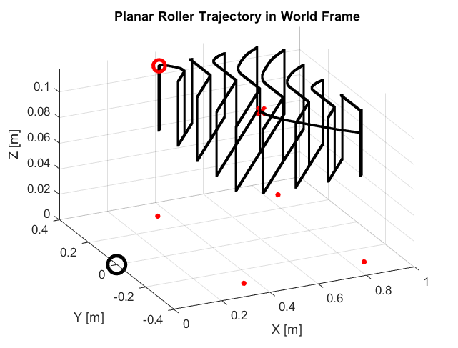
- Generate reference curve via surface intersection or parametric sampling
- Compute desired pose along the curve — position + surface-consistent orientation
For planar molds, the path is generated by intersecting a plane with the surface and sampling along the result. For curved molds, the same approach extends parametrically. The output is a time-parameterized end-effector pose reference for the controller.
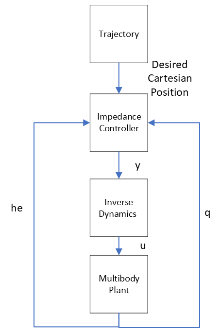
Controller Design
Purely position-based control produces unstable interaction forces when the robot encounters surface variation. Impedance control instead enforces a virtual mass–spring–damper relationship between the actual end-effector motion and the desired trajectory, allowing the robot to comply with the surface rather than fight it.
- Goal: stable contact forces during compaction while tracking the path
- Behavior: compliance under disturbances instead of rigid position enforcement
- Output: desired task-space accelerations → inverse dynamics torques
Results
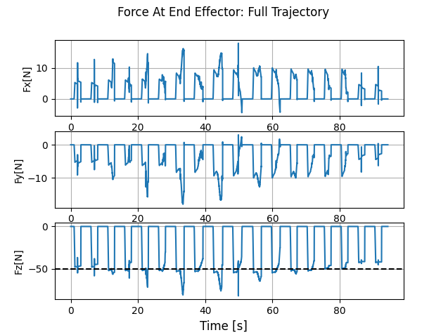
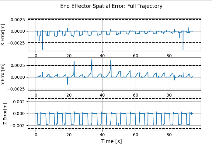
Validation focused on two things: stable interaction under disturbance (push test) and tracking quality along a generated surface pass. Single-pass tuning achieved tight tracking and bounded forces; full-trajectory runs showed force spikes at some transitions, where contact model assumptions break down.
Key outcomes
- Damped disturbance rejection: push test produced smooth recovery without runaway contact forces.
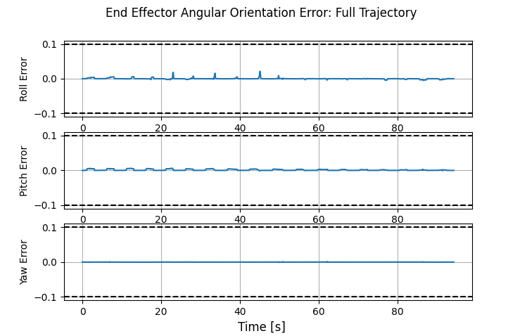
- Tracking (single pass): end-effector pose error stayed tightly bounded during the tuned pass.
- Force regulation: normal-force behavior remained controlled during nominal rolling.
Limitations
- Full-trajectory edge cases: force spikes at some transitions in the longer run.
- Planar assumptions: orientation targets were simplified; a curved mold requires surface-normal alignment and nonzero desired angular rates.
- Simulation-only: real sensing, friction variability, and calibration will change behavior.
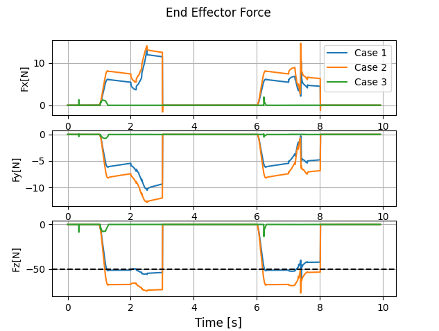
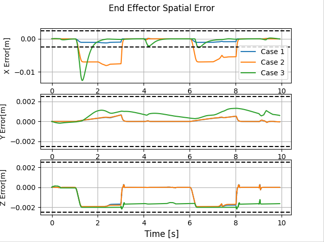
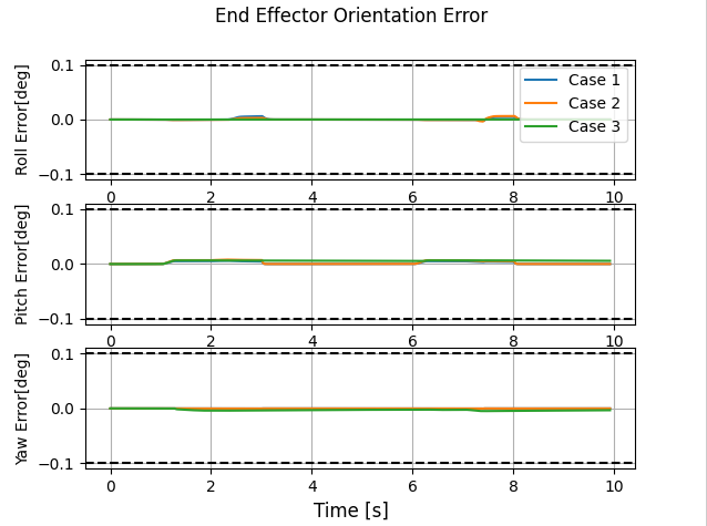
Show full-trajectory plots
Lessons & Next Steps
- Gain scheduling across phases: retune or schedule gains for approach → contact → roll → lift to eliminate transition spikes.
- Curved molds: generate desired pose from surface normals and add nonzero desired angular rates for stable alignment.
- Model realism: add sensor noise, filtering delay, and friction variability to stress-test the controller.
- Compare controllers: benchmark against hybrid force–motion control to quantify tradeoffs.